As there are a lot of errors in the DML M1A1 AIM kit instructions, I am going to point out the areas to take note. I am just covering the problem areas in the instructions only and not the problems associated with fit and accuracy. I will be happy to go through the fit and accuracy issues for those who are interested (most of which are covered in my vBench build).
This post lists out the mistakes that I found and please feel free to add to it if I missed anything. I have started this as a new post to make it easier to refer to.
I hope this will be helpful for those who are building this kit.
Let's get started!
Step 3:
If you want to add the crew heater exhaust plug (part U36 in Step 3), you need to drill out the locating hole on the left side before gluing the hull halves together
 Step 4:
The instructions label two types of track links, H and K. I cant tell the difference between the links provided.
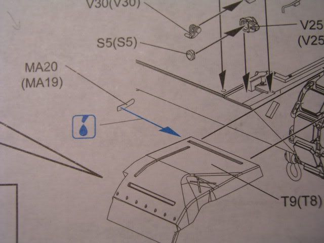
Step 5:
PE parts MA19 and MA20 are incorrectly labeled. MA19 should be on the left front fender and MA20 on the right front fender
Step 4:
The instructions label two types of track links, H and K. I cant tell the difference between the links provided.
Step 5:
PE parts MA19 and MA20 are incorrectly labeled. MA19 should be on the left front fender and MA20 on the right front fender
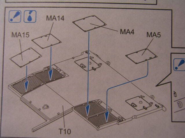
 Step 6:
Engine grill PE parts MA5 and MA15 are incorrectly labeled and should be switched around
Step 6:
Engine grill PE parts MA5 and MA15 are incorrectly labeled and should be switched around
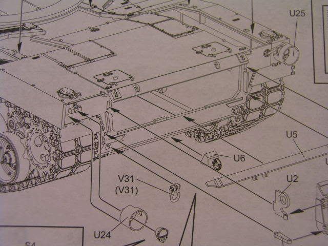
 Step 7:
Rear light guards, U24 and U25 are incorrectly labeled. U24 should on the right and U25 on the left.
Step 7:
Rear light guards, U24 and U25 are incorrectly labeled. U24 should on the right and U25 on the left.
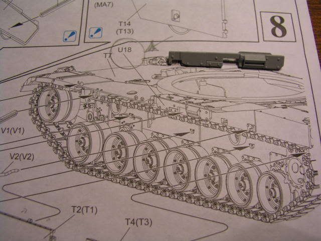
 Step 8:
PE strips MA28 and MA31 do not fit. MA28 is too long and MA31 is too short.
Take note of part U18. In the instructions U18 is drawn as part of the hull and not as a part to be glued. You need to attach this part.
Step 8:
PE strips MA28 and MA31 do not fit. MA28 is too long and MA31 is too short.
Take note of part U18. In the instructions U18 is drawn as part of the hull and not as a part to be glued. You need to attach this part.
 Step 10:
Before gluing the turret halves together, you need to drill out locating holes for the EPLRS antenna, part N38 (in Step 13) and part Q2 (in Step 14). Instructions fail to point this out in Step 10.
Step 10:
Before gluing the turret halves together, you need to drill out locating holes for the EPLRS antenna, part N38 (in Step 13) and part Q2 (in Step 14). Instructions fail to point this out in Step 10.
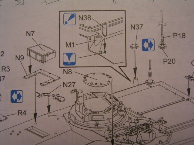
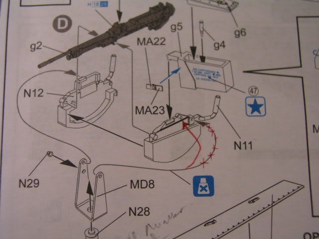
 Step 11:
Sub assembly D: Metal bracket MD8 should attach to the little plastic protrusion on the left side of part N11
Step 11:
Sub assembly D: Metal bracket MD8 should attach to the little plastic protrusion on the left side of part N11
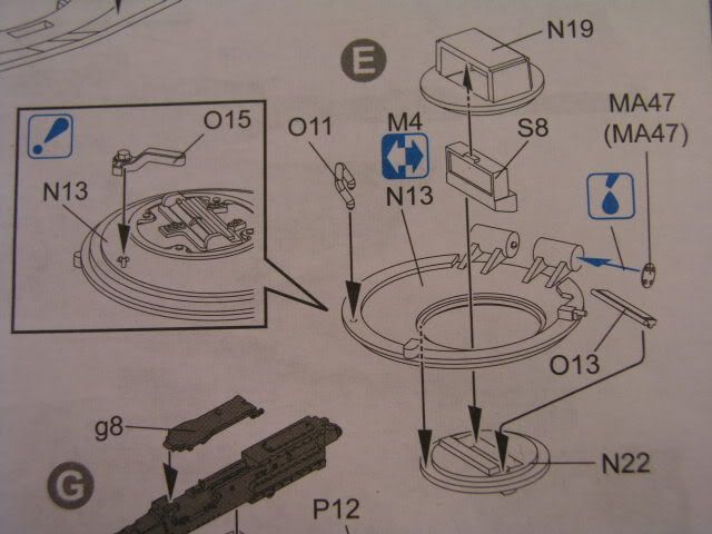
 Sub assembly E: PE part MA47 should go on either end of the hatch hinge. One on the loaders hatch hinge and the other one on the end of the hinge on the turret roof. The instructions only show the location for one of the PE part and not the other.
Two types of loaders hatch is provided, M4 and N13. They are located on different sprues and the instructions is not clear on the option available.
Sub assembly E: PE part MA47 should go on either end of the hatch hinge. One on the loaders hatch hinge and the other one on the end of the hinge on the turret roof. The instructions only show the location for one of the PE part and not the other.
Two types of loaders hatch is provided, M4 and N13. They are located on different sprues and the instructions is not clear on the option available.
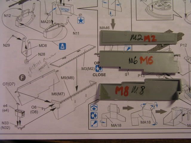
 Sub assembly F: Turret stowage bin rear panel, parts M6 and M7 are incorrectly labeled. Part M6 should be on the right side and M7 on the left side.
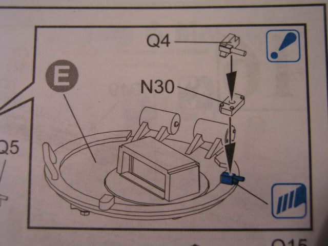
 Step 12:
If you choose the version with the non-smooth blow off panels, then the loaders hatch stop must be removed and replaced with parts N30 and Q4. The instructions is wrong on the position of the new hatch stop. Parts N30 and Q4 should be located on the hatch near the hinge where there is a small notch in the reinforced hatch lip.
Step 12:
If you choose the version with the non-smooth blow off panels, then the loaders hatch stop must be removed and replaced with parts N30 and Q4. The instructions is wrong on the position of the new hatch stop. Parts N30 and Q4 should be located on the hatch near the hinge where there is a small notch in the reinforced hatch lip.
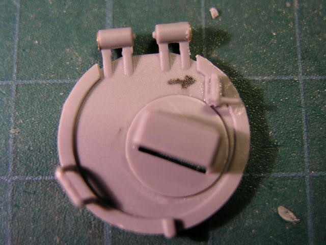
Correct location of the hatch stop should be like this
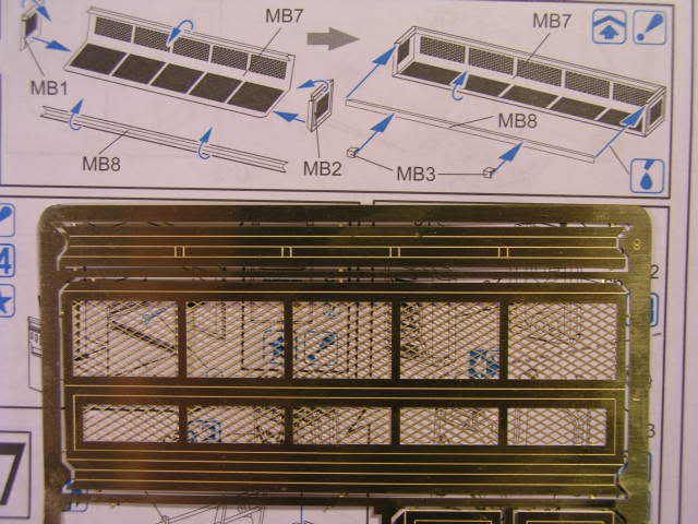
 Step 16:
The turret bustle rack extension is only applicable for Desert Rogues. Make sure you fold the PE part MB7 with the score line on the outside of the fold.
Step 16:
The turret bustle rack extension is only applicable for Desert Rogues. Make sure you fold the PE part MB7 with the score line on the outside of the fold.
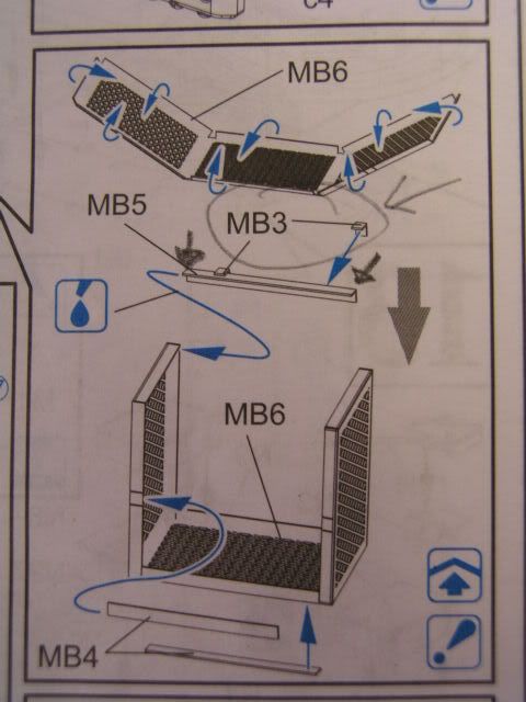
 Step 17:
The jerrycan rack holder frame mounting points, part MB3 should be located the either end of part MB5.
Step 17:
The jerrycan rack holder frame mounting points, part MB3 should be located the either end of part MB5.
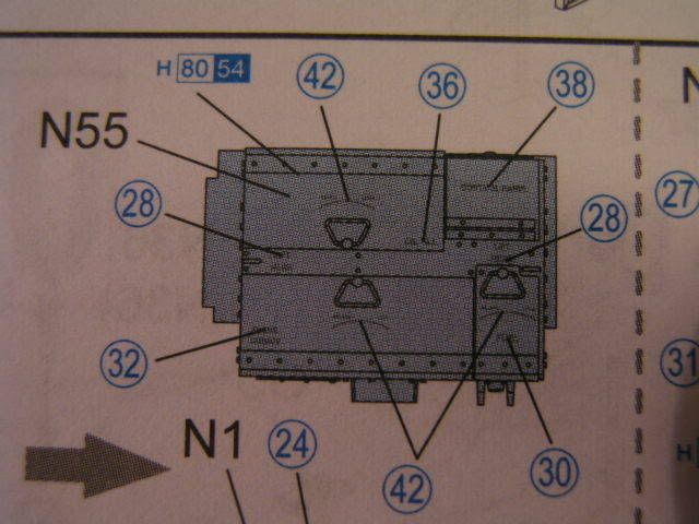
 Step 18:
All the decals on the top of the EAPU are orientated the wrong way and should be turned 180 degrees. Decal #42 for the Fuel hatch is also too long (the one on top of decal #30)
Step 18:
All the decals on the top of the EAPU are orientated the wrong way and should be turned 180 degrees. Decal #42 for the Fuel hatch is also too long (the one on top of decal #30)
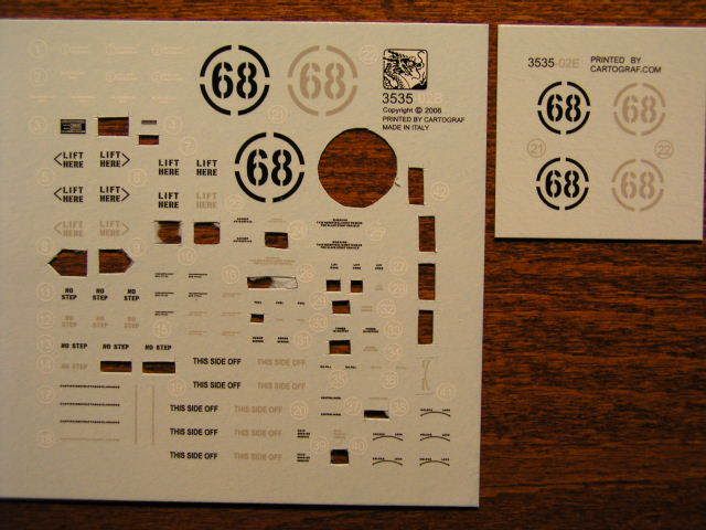
 Decals
 number #21 and #22 (the number 68 in the curcle) on the medium sized decal sheet (marked 3535-02B) are too large. Use the same numbered decals on the smaller decal sheet (marked 3535-02E). Also I have seen the black colored #21 used on a three tone camouflage vehicle.
Decals
Decals number #21 and #22 (the number 68 in the curcle) on the medium sized decal sheet (marked 3535-02B) are too large. Use the same numbered decals on the smaller decal sheet (marked 3535-02E). Also I have seen the black colored #21 used on a three tone camouflage vehicle.
__________________
 Adrian Cronauer [imitating Walter Cronkite]:
 I just want to begin by saying to Roosevelt E. Roosevelt, what it is, what it shall be, what it was. The weather out there today is hot and shitty with continued hot and shitty in the afternoon. Tomorrow a chance of continued crappy with a pissy weather front coming down from the north. Basically, it's hotter than a snake's ass in a wagon rut.


 Threaded Mode
