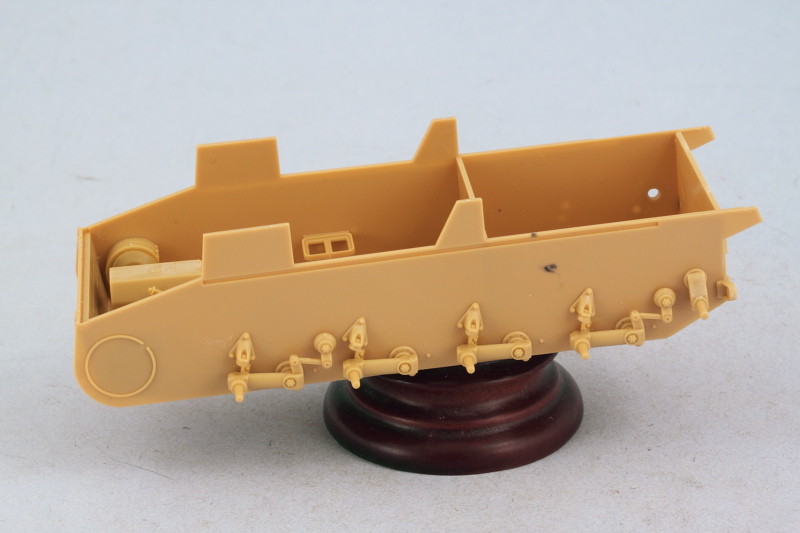
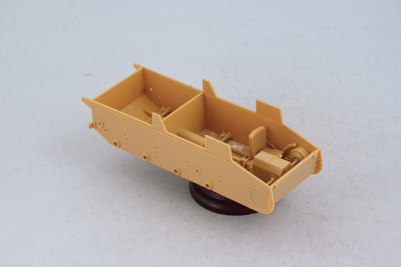
Work continued from yesterday's efforts with Steps 4 and 5 which deal with the suspension elements.
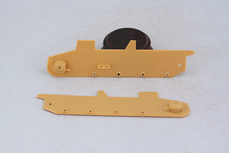
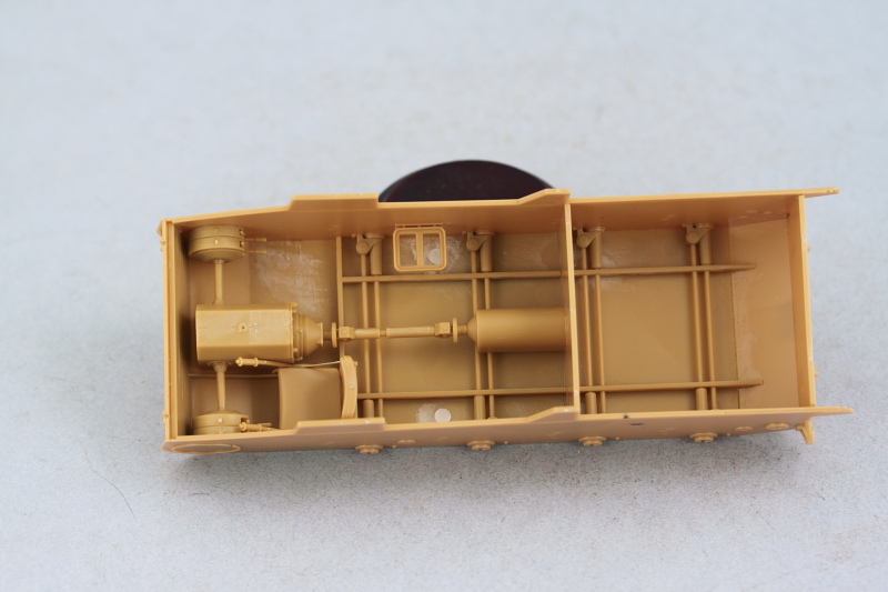
Step 4 adds a lot of little parts along with the suspension arms for the road wheels. The instructions direct you to remove 3.1mm from the portions of the arms that mount into the hull, so some surgery is required on all 8 arms. This is due to the fact that the addition of the torsion bar parts on the hull interior (presumably not present in Bronco's earlier Pz II-D kit) blocks off those openings in the hull sides. Easily done with a ruler to mark the cut line, then snip off with sprue cutters and sand down the ends where necessary. The arm bump stops, parts B40, have mount pins on their backs but the pins are too long for them to fit flush, so some sanding is necessary there as well. The idler mount arms were dry-fit only as I need them to remain movable to allow for the workable track tensioning down the road.
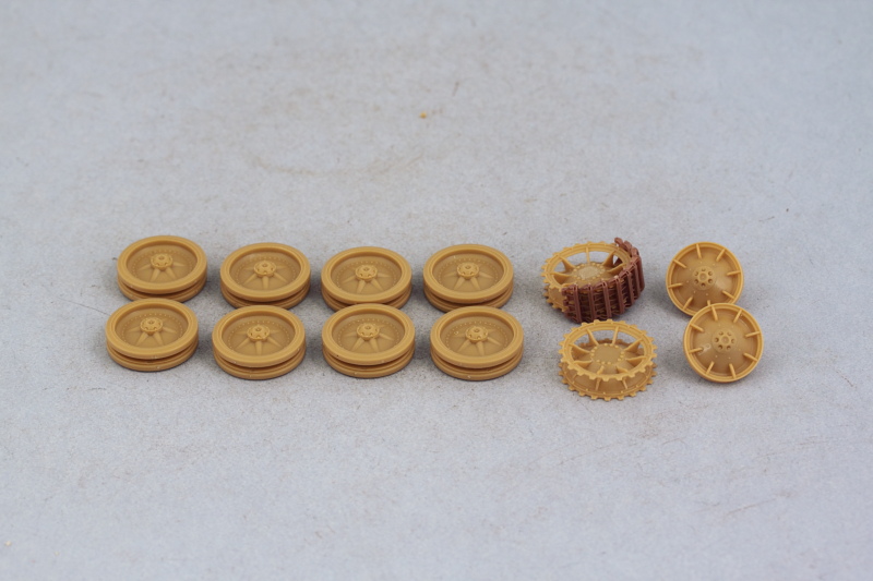
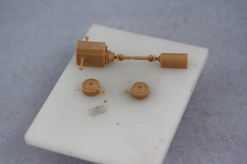
Step 5 deals with the assembly of the road wheels, sprockets, and idlers. The road wheels are separate halves with separate rubber rims as well...and each part has 4 attachment points to be cleaned up. The wheel hubs also had some flash on their inner surfaces that had to be removed, so quite a bit of clean up effort involved with them as a result. The rubber rims fit tightly with a friction fit, so they can be removed easily later on for separate painting but care will be needed to avoid any paint on the insides of the rims and the hubs causing a disruption.
The sprockets assembled easily and I used a run of 10 links from the MK set to ensure the sprocket teeth lined up correctly and would play nice with the tracks later on. That same run was used to test the gap fit on the road wheels as well as the idlers. On the idlers, the front half has small tabs that are supposed to fit into the back halves but the tabs are too tall and have to be trimmed down to all the front half to fit flush at the right gap interval.
Bronco designed the idlers to have a small insert (B21) that's meant to help create a friction fit with the idler swing arm. It's the same part that goes inside each of the road wheels but the difference with the idler arm is that it isn't tapered like the road wheel arms...so it won't fit. It's a good thing I tested that before committing to glue on the idler hub caps, otherwise it would've been harder to fix. The solution is to taper the points of the idler mount arms to match the taper on the road wheel suspension arms with careful trimming/sanding. Don't add part B23 (the idler tension bolt) at this stage unless you're sure about the position you need for the idler...I'm not, so that will get added later.
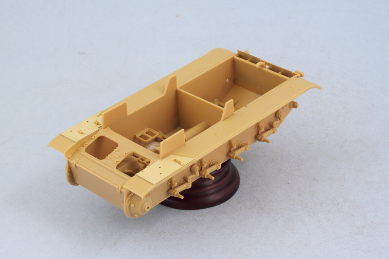
A test fit with all the parts from Step 5 was carried out to make sure everything lined up properly. Installation will occur later on after painting.
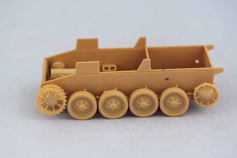
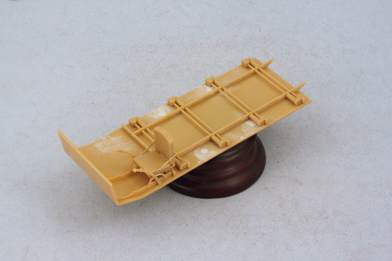
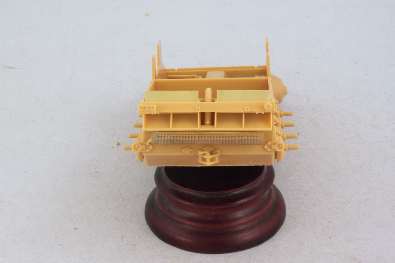
Next up will be working on the rear hull details and then on to the fenders.


 Hybrid Mode

